- 您现在的位置:买卖IC网 > Sheet目录1194 > ADT7473ZEVB (ON Semiconductor)BOARD EVALUATION FOR ADT7473
�� �
�
�ADT7473�
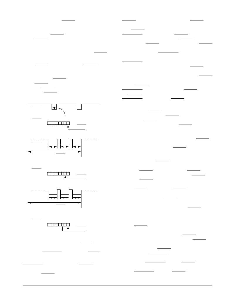
�45.52� ms,� Bit� 1� of� the� THERM� timer� is� set� and� Bit� 0�
�becomes� the� LSB� of� the� timer� with� a� resolution� of� 22.76� ms�
�(see� Figure� 32).�
�When� using� the� THERM� timer,� be� aware� of� the� following.�
�After� a� THERM� timer� read� (0x79):�
�1.� The� contents� of� the� timer� are� cleared� on� read.�
�2.� The� F4P� bit� (Bit� 5)� of� Interrupt� Status� Register� 2�
�needs� to� be� cleared� (assuming� that� the� THERM�
�timer� limit� has� been� exceeded).�
�If� the� THERM� timer� is� read� during� a� THERM� assertion,�
�then� the� following� happens:�
�1.� The� contents� of� the� timer� are� cleared.�
�2.� Bit� 0� of� the� THERM� timer� is� set� to� 1� (because� a�
�THERM� assertion� is� occurring).�
�3.� The� THERM� timer� increments� from� 0.�
�4.� If� the� THERM� timer� limit� (Register� 0x7A)� =� 0x00,�
�the� F4P� bit� is� set.�
�THERM�
�THERM� timer� events.� Register� 0x7A� is� the� THERM� timer�
�limit� register.� This� 8-bit� register� allows� a� limit� from� 0� sec�
�(first� THERM� assertion)� to� 5.825� sec� to� be� set� before� an�
�SMBALERT� is� generated.� The� THERM� timer� value� is�
�compared� with� the� contents� of� the� THERM� timer� limit�
�register.� If� the� THERM� timer� value� exceeds� the� THERM�
�timer� limit� value,� the� F4P bit (Bit� 5)� of� Interrupt� Status�
�Register� 2� is� set� and� an� SMBALERT� is� generated.� The� F4P�
�bit� (Bit� 5)� of� Interrupt� Mask� Register� 2� (0x75)� masks� out� the�
�SMBALERT� if� this� bit� is� set� to� 1;� however,� the� F4P� bit� of�
�Interrupt� Status� Register� 2� still� is� set� if� the� THERM� timer�
�limit� is� exceeded.�
�Figure� 33� is� a� functional� block� diagram� of� the� THERM�
�timer,� limit,� and� associated� circuitry.� Writing� a� value� of� 0x00�
�to� the� THERM� timer� limit� register� (0x7A)� causes� an�
�SMBALERT� to� be� generated� on� the� first� THERM� assertion.�
�A THERM� timer� limit� value� of� 0x01� generates� an�
�SMBALERT� once� cumulative� THERM� assertions� exceed�
�45.52� ms.�
�Configuring� the� THERM� Behavior�
�THERM�
�TIMER�
�(REG.� 0x79)�
�0� 0� 0� 0� 0� 0� 0� 1�
�7� 6� 5� 4� 3� 2� 1� 0�
�THERM� ASSERTED�
�?� 22.76� ms�
�1.� Configure� Pin� 9� as� a� THERM� timer� input.� Setting�
�Bit� 1� (THERM� timer� enable)� of� Configuration�
�Register� 3� (0x78)� enables� the� THERM� timer�
�monitoring� functionality.� This� is� disabled� on� Pin� 9�
�by� default.� Setting� Bit� 0� and� Bit� 1� (PIN9FUNC)� of�
�THERM�
�ACCUMULATE� THERM� LOW�
�ASSERTION� TIMES�
�Configuration� Register� 4� (0x7D)� enables� THERM�
�timer/output� functionality� on Pin 9� (Bit� 1� of�
�Configuration� Register� 3,� THERM,� must� also� be�
�set).� Pin� 9� can� also� be� used� as� TACH4.� Setting�
�Bit� 5,� Bit� 6,� and� Bit� 7� of� Configuration� Register� 5�
�(0x7C)� makes� THERM� bidirectional.� This� means�
�THERM�
�TIMER�
�(REG.� 0x79)�
�0� 0� 0� 0� 0� 0� 1� 0�
�7� 6� 5� 4� 3� 2� 1� 0�
�THERM� ASSERTED�
�?� 45.52� ms�
�that� if� the� appropriate� temperature� channel� exceeds�
�the� THERM� temperature� limit,� the� THERM� output�
�asserts.� If� the� ADT7473� is� not� pulling� THERM� low,�
�but� THERM� is� pulled� low� by� an� external� device�
�(such� as� a� CPU� overtemperature� signal),� the�
�THERM�
�ACCUMULATE� THERM� LOW�
�ASSERTION� TIMES�
�THERM� timer� also� times� THERM� assertions.� If�
�Bit� 5,� Bit� 6,� and� Bit� 7� of� Configuration� Register� 5�
�(0x7C)� are� set� to� 0,� THERM� is� set� as� a� timer� input�
�only.�
�2.� Select� the� desired� fan� behavior� for� THERM� timer�
�events.� Assuming� the� fans� are� running,� setting�
�THERM�
�TIMER�
�(REG.� 0x79)�
�0� 0� 0� 0� 0� 1� 0� 1�
�7� 6� 5� 4� 3� 2� 1� 0�
�THERM� ASSERTED�
�?� 113.8� ms�
�(91.04� ms� +� 22.76� ms)�
�Bit� 2� (BOOST)� of� Configuration� Register� 3� (0x78)�
�causes� all� fans� to� run� at� 100%� duty� cycle� whenever�
�THERM� is� asserted.� This� allows� fail-safe� system�
�cooling.� If� this� bit� is� 0,� the� fans� run� at� their� current�
�settings� and� are� not� affected� by� THERM� events.� If�
�Figure� 32.� Understanding� the� THERM� Timer�
�Generating� SMBALERT� Interrupts� from� THERM� Timer�
�Events�
�The� ADT7473/ADT7473� ?� 1� can� generate� an�
�SMBALERT� when� a� programmable� THERM� timer� limit� is�
�exceeded.� This� allows� the� system� designer� to� ignore� brief,�
�infrequent� THERM� assertions,� while� capturing� longer�
�the� fans� are� not� already� running� when� THERM� is�
�asserted,� the� fans� do� not� run� at� full� speed.�
�3.� Select� whether� THERM� timer� events� should�
�generate� SMBALERT� interrupts.� Bit� 5� (F4P)� of�
�Interrupt� Mask� Register� 2� (0x75),� when� set,� masks�
�out� the� SMBALERT� when� the� THERM� timer� limit�
�value� is� exceeded.� This� b� it should� be� cleared� if�
�SMBALERTis� based� on� THERM� events� required.�
�http://onsemi.com�
�23�
�发布紧急采购,3分钟左右您将得到回复。
相关PDF资料
ADT7475EBZEVB
BOARD EVALUATION FOR ADT7475
ADT7476EBZEVB
BOARD EVALUATION FOR ADT7476
ADT7490ZEVB
BOARD EVALUATION FOR ADT7490
ADZS-21262-1-EZEXT
BOARD DAUGHTER FOR ADSP-21262
ADZS-BF-EZEXT-1
BOARD DAUGHTER ADSP-BF533/561KIT
ADZS-BFAV-EZEXT
BOARD DAUGHT ADSP-BF533,37,61KIT
ADZS-BFSHUSB-EZEXT
BOARD DAUGHTER EZ EXTENDER
ADZS-BRKOUT-EX3
ADZS-BRKOUT-EX3
相关代理商/技术参数
ADT7475
制造商:ONSEMI 制造商全称:ON Semiconductor 功能描述:dBCOOL Remote Thermal Monitor and Fan Controller
ADT7475_1110
制造商:ONSEMI 制造商全称:ON Semiconductor 功能描述:dbCOOL Remote Thermal Monitor and Fan Controller
ADT7475ARQZ
功能描述:马达/运动/点火控制器和驱动器 MLTCH TDM FAN CTRLR RoHS:否 制造商:STMicroelectronics 产品:Stepper Motor Controllers / Drivers 类型:2 Phase Stepper Motor Driver 工作电源电压:8 V to 45 V 电源电流:0.5 mA 工作温度:- 25 C to + 125 C 安装风格:SMD/SMT 封装 / 箱体:HTSSOP-28 封装:Tube
ADT7475ARQZ-REEL
功能描述:板上安装温度传感器 MULTICH TDM FAN CTRL RoHS:否 制造商:Omron Electronics 输出类型:Digital 配置: 准确性:+/- 1.5 C, +/- 3 C 温度阈值: 数字输出 - 总线接口:2-Wire, I2C, SMBus 电源电压-最大:5.5 V 电源电压-最小:4.5 V 最大工作温度:+ 50 C 最小工作温度:0 C 关闭: 安装风格: 封装 / 箱体: 设备功能:Temperature and Humidity Sensor
ADT7475ARQZ-REEL7
功能描述:IC REMOTE THERMAL CTRLR 16QSOP RoHS:是 类别:集成电路 (IC) >> PMIC - 热管理 系列:dBCool® 标准包装:1 系列:- 功能:温度监控系统(传感器) 传感器类型:内部和外部 感应温度:-40°C ~ 125°C,外部传感器 精确度:±2.5°C 本地(最大值),±5°C 远程(最大值) 拓扑:ADC,比较器,寄存器库 输出类型:2 线 SMBus? 输出警报:无 输出风扇:无 电源电压:2.7 V ~ 5.5 V 工作温度:-40°C ~ 125°C 安装类型:表面贴装 封装/外壳:SOT-23-8 供应商设备封装:SOT-23-8 包装:Digi-Reel® 其它名称:296-22675-6
ADT7475ARQZ-RL7
功能描述:板上安装温度传感器 MLTCH TDM FAN CTRLR
RoHS:否 制造商:Omron Electronics 输出类型:Digital 配置: 准确性:+/- 1.5 C, +/- 3 C 温度阈值: 数字输出 - 总线接口:2-Wire, I2C, SMBus 电源电压-最大:5.5 V 电源电压-最小:4.5 V 最大工作温度:+ 50 C 最小工作温度:0 C 关闭: 安装风格: 封装 / 箱体: 设备功能:Temperature and Humidity Sensor
ADT7475EBZEVB
功能描述:BOARD EVALUATION FOR ADT7475 RoHS:否 类别:编程器,开发系统 >> 过时/停产零件编号 系列:dBCool® 标准包装:1 系列:- 传感器类型:CMOS 成像,彩色(RGB) 传感范围:WVGA 接口:I²C 灵敏度:60 fps 电源电压:5.7 V ~ 6.3 V 嵌入式:否 已供物品:成像器板 已用 IC / 零件:KAC-00401 相关产品:4H2099-ND - SENSOR IMAGE WVGA COLOR 48-PQFP4H2094-ND - SENSOR IMAGE WVGA MONO 48-PQFP
ADT7476
制造商:AD 制造商全称:Analog Devices 功能描述:dBCool Remote Thermal Controller and Voltage Monitor